Hydraulic stop wheel
The hydraulic stop wheel is a device used to control the axial movement of the rotary kiln body
Classification:
Key words: casting and forging
Sales Hotline:
The hydraulic stop wheel is a device used to control the axial movement of the rotary kiln body, mainly applied in industries such as cement, metallurgy, and chemical engineering. Its function is to ensure that the kiln body can slide up and down stably under its own weight, thereby extending the service life of the equipment and reducing maintenance workload.
Working Principle
The hydraulic stop wheel pushes the stop wheel through the piston in the hydraulic cylinder, allowing the rotary kiln cylinder to achieve stable up and down movement under its own weight. When the hydraulic pressure pushes the piston upward, the weight of the kiln body causes it to slide down, ensuring the stable up and down movement of the rotary kiln cylinder and achieving uniform wear of the rolling ring and support wheel.
Structural Composition
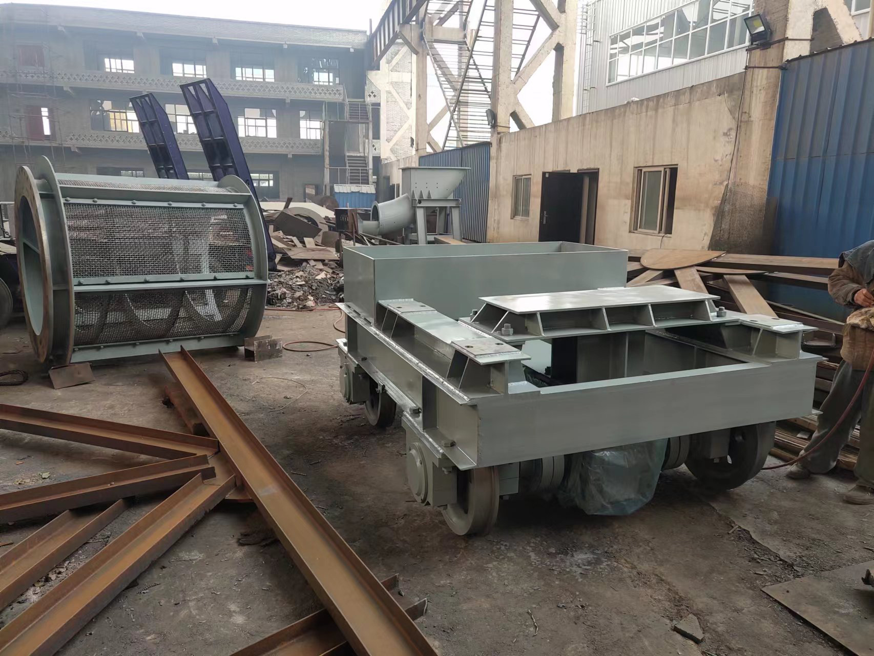
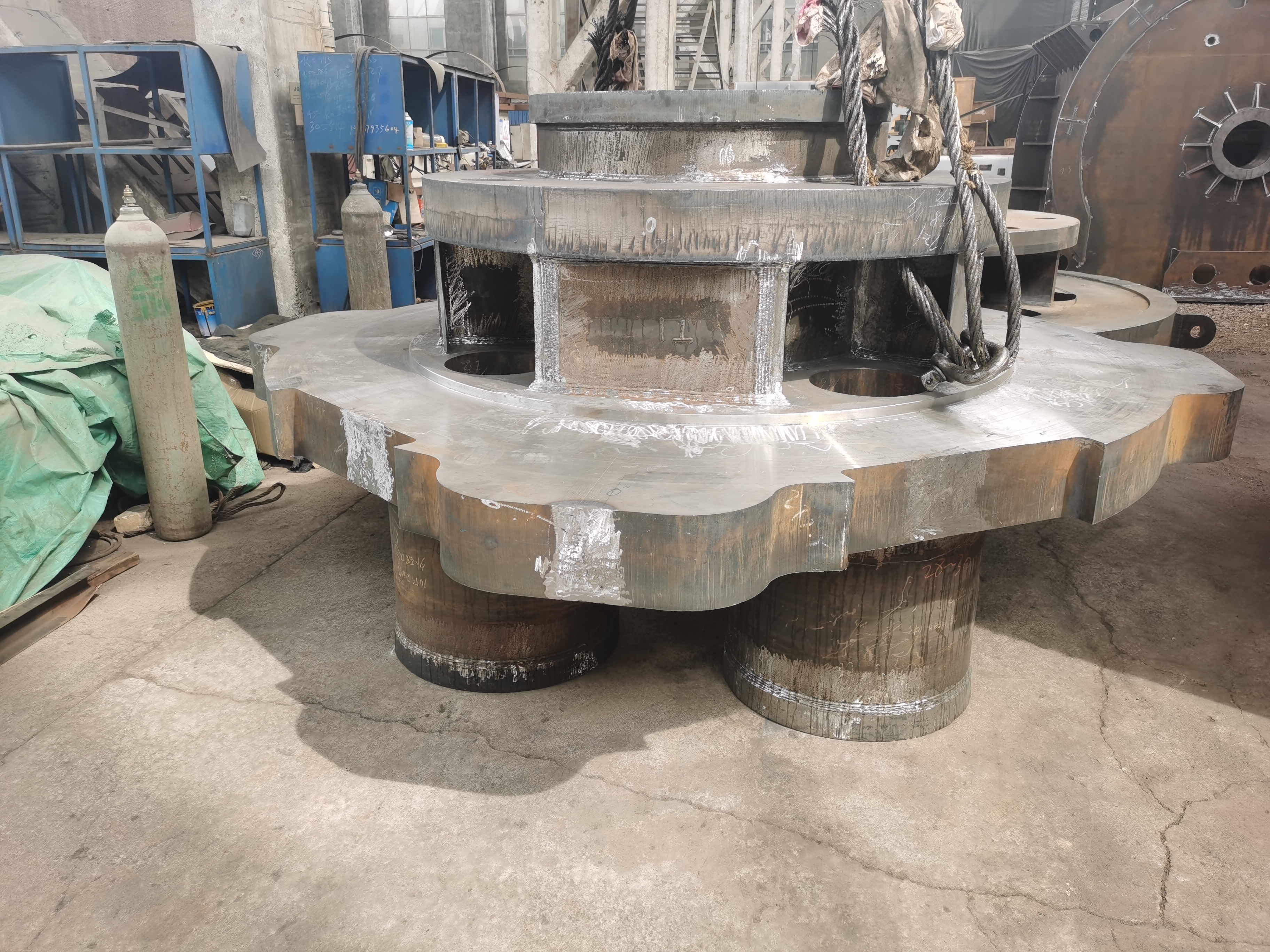
The hydraulic stop wheel system mainly consists of the hydraulic stop wheel cylinder, stop wheel, moving seat, guide shaft, support, and other components. The piston rod in the hydraulic stop wheel cylinder pushes the stop wheel, which contacts the inclined surface of the rolling ring, thereby pushing the rolling ring to lift the rotary kiln cylinder. Both the stop wheel and the hydraulic stop wheel cylinder are mounted on the support, while the moving seat reciprocates along the guide shaft.
Performance Characteristics
High pressure and low flow: The hydraulic stop wheel system has a very high oil pressure (usually 7 to 8 MPa), but the distance the kiln body moves upward is very small (50 to 100 mm), and the moving speed is also slow (0.3 to 0.5 mm/min). This characteristic of high pressure and low flow requires the hydraulic cylinder to have sufficient strength and high-pressure sealing performance.
Precision machining: Due to the high-pressure characteristics of the system, there are strict requirements for the machining accuracy of each component.
Automatic control: The system usually includes control elements such as electromagnetic reversing valves to control the movement direction of the hydraulic stop wheel cylinder, achieving automated control.
| Soil type of stratum | Soft rock and clay |
| Minimum turning curve radius | 250m |
| Maximum slope | 3.50% |
| Total length | 9m (approximately) |
| Total weight | 370 tons (approximately) |
| Excavation diameter | 6,400mm |
| Outer diameter of front shield | 6,390mm |
| Outer diameter of the shield | 6,380mm |
| Outer diameter of tail shield | 6,370mm |
| Shield tail gap | 45mm |
| Total equipment power | 1650kW (approximately) |
| Maximum excavation speed | 80mm/min |
| Maximum thrust | 42575kN |
| Shield tail seal | 3 rows of sealing brushes |
| Soil pressure sensor | Three, on the earth pressure wall |
| Hydraulic sensor | 4, 1 for each propulsion cylinder group |
| Main bearing life | 10000 hours, according to DIN ISO 281, L10 |
| Maximum work pressure | 3bar |
| Maximum design pressure | 4.5bar |
| Including the total length of supporting facilities | 72m |
Related Products
Consultation
If you are interested in our products, please leave your email, we will contact you as soon as possible, thank you!


